SPD (Surge Protection Device)
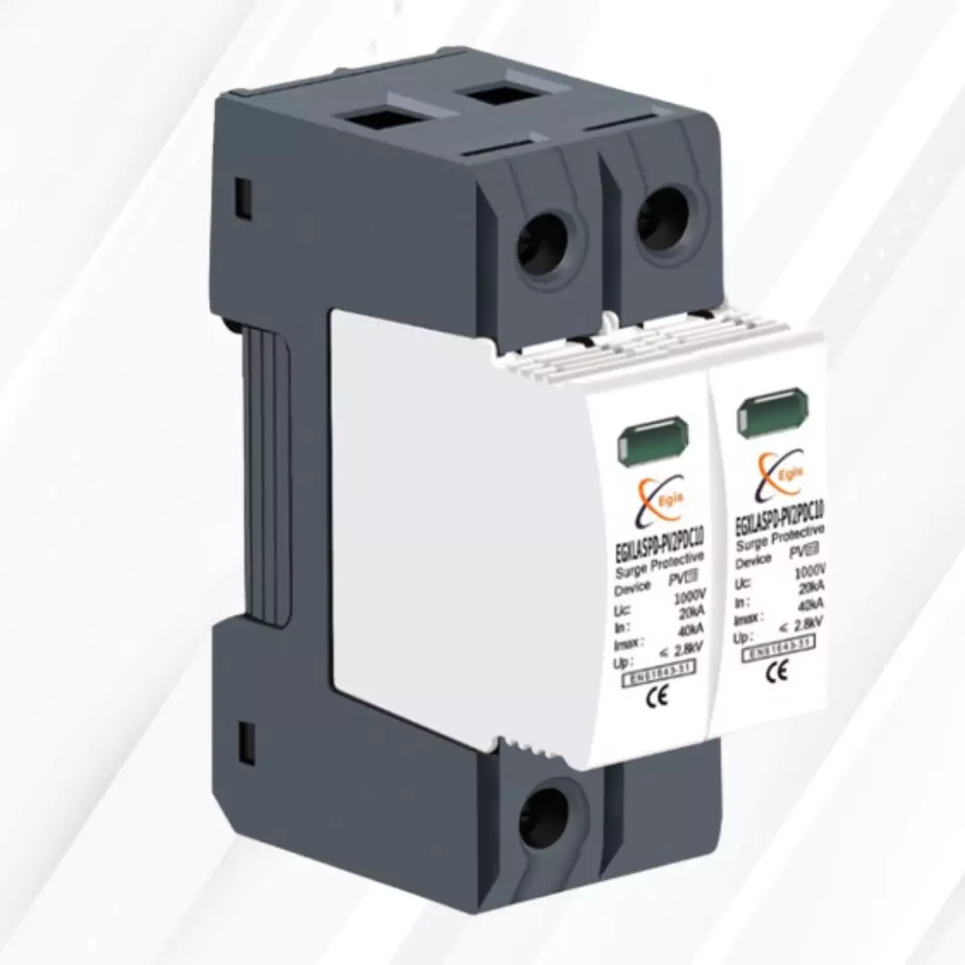
Surge protective device, protect against lightning surge voltages in solar system (photovoltaic power supply system). These units must be installed in parallel on the dc networks to be protected and provide common and different models protection. Its installed location are recommended at both ends of the dc power supplyline (solar panel side and inverter/converter side), especially if the line routing is external and long. High energy MOVS equipped with specific thermal disconnectors and related failure indicators.
| EGXLDCSPD–PV (A–B) Series | EGXLDCSPD–PV (A–B) | ||||||
|---|---|---|---|---|---|---|---|
| PVDC-specific | EN61643-31 | ||||||
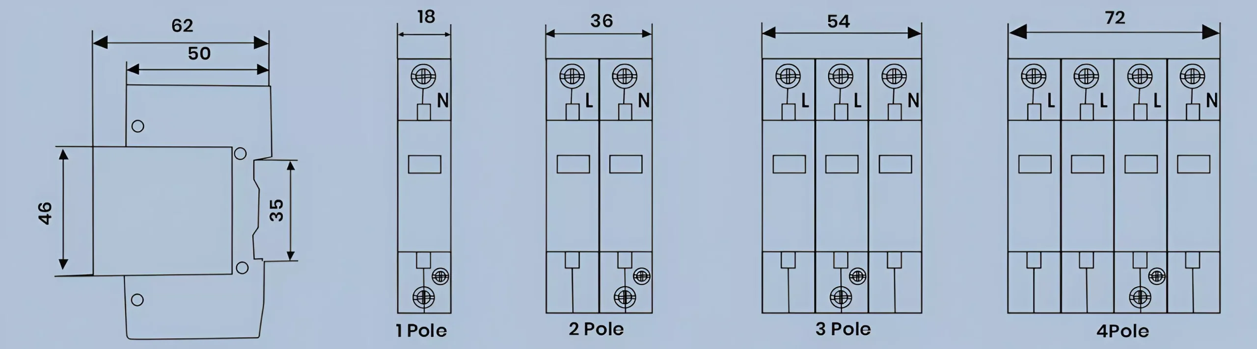
| Pole | 2P | 2P | 2P | 2P | 3P | 3P | 3P (CUSTOMIZED) |
| Electrical parameter | |||||||
| Classified test | II | II | II | II | II | II | II |
| Uoc max (VDC) | 500 | 600 | 800 | 1000 | 1000 | 1200 | 1500 |
| 1 | 500 | 600 | 800 | 1000 | 1000 | 1200 | 1500 |
| In (8/20)µs (kA) | 20 | 20 | 20 | 20 | 20 | 20 | 20 |
| Ima x (8/20)µs (kA) | 40 | 40 | 40 | 40 | 40 | 40 | 40 |
| Up (kV) | 2.8 | 2.8 | 3.2 | 3.8 | 3.8 | 3.8 | 5.5 |
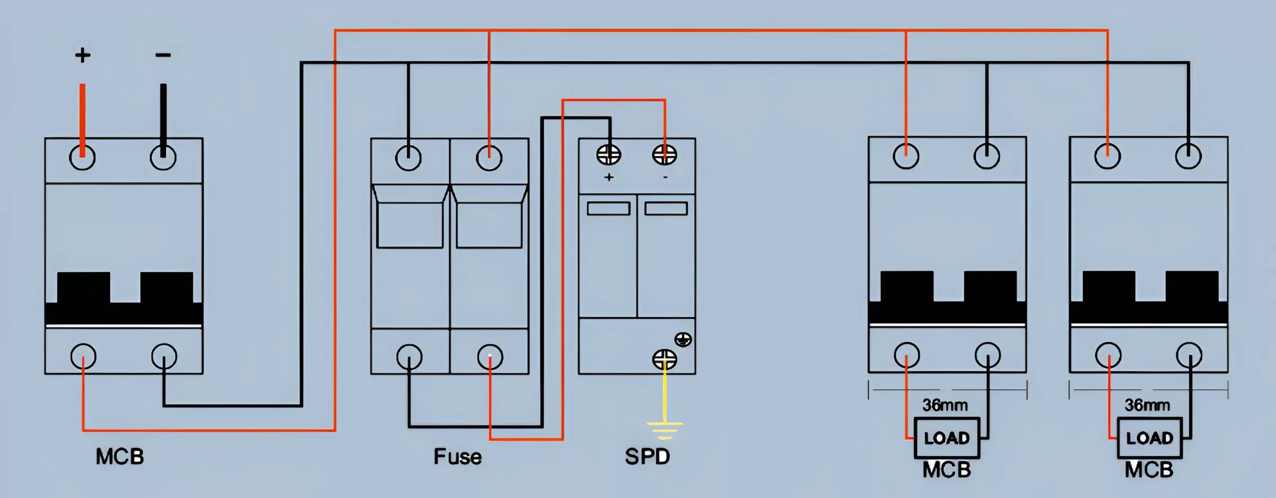
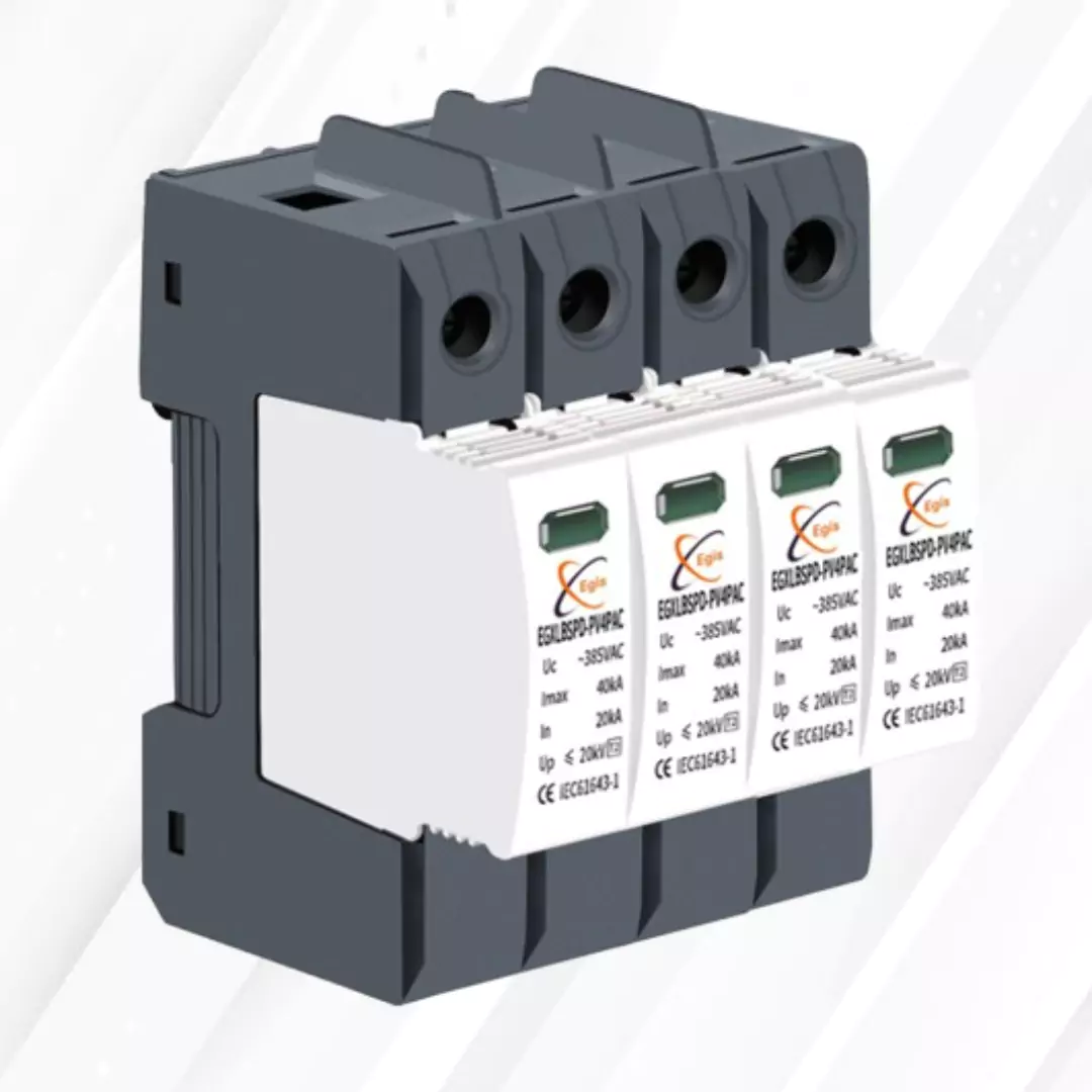
SUPI(D, C, B) 5 series surge protection device (in short: SPD, alias; surge suppressor, surge arrester) is suitable for TN-S, TN-C-S, TI IT etc. power supply system of AC 50/60HZ, <380V, installed on the joint of LPZI or LP22 and LP23, it’s designed according to IEC61643-1, GB18802.1, it adopts 35mm standard rail, there is a failure release mounted on the module of surge protection device. When the SPD fails in A breakdown for over-heat and over- current, the failure release will help electric equipments separate from the power supply system and give the indication signal, green means normal, red means abnormal, it also could be replaced for the module when has operating voltage.
- Could be replaced for the module not need power off.
- Maximum cu rrent of endure the lightning stroke 40KA (8/20us).
- Time of response <25ns.;
- The color of visible window shows operating status, green means normal, red means abnormal.
| Protection Level B,C,D Grade | D.C.B | |||||
|---|---|---|---|---|---|---|
| Rated Operating Voltage Un (V~) | 380V / 220V | |||||
| Maximum Continuous Operating Voltage Un (V~) | 275V | 275V | 385V | 385V | 385V | 420V |
| Voltage Protection Level Up (V~) kV | ≤2.0 | ≤2.0 | ≤2.0 | ≤2.0 | ≤2.2 | ≤2.8 |
| Nominal Discharge Current in µs kA | 10 | 20 | 20 | 30 | 40 | 60 |
| Maximum Discharge Current Imax µs kA | 20 | 40 | 40 | 60 | 80 | 100 |
| Response Time (ns) | <25 | |||||
| Test Standard | IEC61643.1, GB18802.1 | |||||
| Operating Environment (°C) | -40°C ~ +85°C | |||||
| Max Connection Line | 35mm² hard wire / 35mm² strand wire copper line | |||||
| Recommended Connection Line | 16mm² hard wire / 25mm² strand wire copper line | |||||
| Installation | Standard Rail 35mm | |||||
| Material of Outer Covering | Burning-proof Nylon | |||||